Application Note Courtesy of Damalini
Straightness measurement is done on a large number of applications, for example balks, rolls, machine
constructions, transportation lines etc.
The basic principle for straightness measurement
The basic principle for straightness measurement is that all measurement values will show the position of the detector unit relative the laser beam. To be able to use the values for adjustment and documentation it is needed to set absolute references (zero points). These can be points on the measured object or the horizontal level.
Horizontal level
When using horizontal reference, the laser beam is leveled according to the vials on the D22 laser transmitter. When the measured object is the reference, the laser beam is leveled to the detector positioned
at the reference points. This leveling is always done according to the same principle: zero setting of the
laser.
Straightness measurement with S and M units
It is also possible to perform a straightness measurement with the S and M units from a shaft alignment system (i.e. no separate laser transmitter is needed). The S unit is used as reference transmitter and the M
unit is used as detector. In this case though, it is not possible to use horizontal reference.
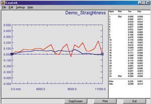 |  | Straightness measurement with first and last measuring
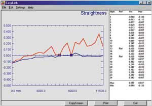
point as reference (EasyLink). | Straightness measurement with reference points moved
(EasyLink) |
|