|
The procedure for doing reverse dial indicator alignment is not a difficult one. There are several steps which need to be taken for a successful alignment job.
Step 1
Familiarize with terms, techniques and procedure.
*follow all safety rules and procedures
Step 2
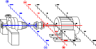
Learn about the machine you are aligning.
-
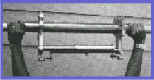
Visually check coupling, pipehangers, base bolts, coupling spacing etc.
-
Check for coupling & shaft run out.
Step 3
Know the characteristics of your tool. Perform a Sag Check
-
A sag check is a test that determines the amount an indicator bracket will sag at a given distance.
-
How to perform a sag check:
Clamp the brackets on a sturdy piece of pipe the same distance they will be when placed on the equipment. Zero both indicators on top, then rotate to the bottom. The difference between the top and bottom reading is the sag.
Step 4
Prepare the machine.
a. Remove all existing shims from under the feet
-if old shims are to be used, clean them thoroughly.
-always use minimum amount of shims.
b. Clean the base thoroughly.
-scrape and file away all rust, nicks, and burrs
c. Examine the base bolts and holes.
-retap if necessary
-replace bolts if necessary
Step 5
Clean mounting surface, file off nicks and burrs.
b. Check indicators for sticking and loose needle.
c. Aim indicator stem directly toward center line of shaft.
Step 6
Measurement
-measure distance between the two indicators.
-measure distance between indicator and front feet.
-measure distance between front and back feet.
Step 7
Layout graph paper
-mark indicator position
-mark feet position.
-remember to mark + and - signs (this eliminates confusion)
example: graph layout
Step 8
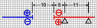
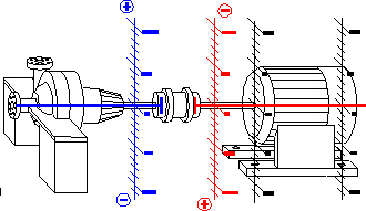
Preliminary Horizontal Move
-
The horizontal move is the part of the alignment process that aligns the shaft's centerlines from side to side. View the machine from the pump end, zero the indicators on the left, and then rotate and read on the right. Make sure that you always view the pump from the same direction in order for you to keep the left and right directions correct. There is no sag compensation on the horizontal move.
For Example:
the indicator on the pump reads -8
the indicator on the motor reads +10
The shafts are collinear at 1/2 the Total Indicator Reading.
These indicator readings mean that you need to move the motor:
front foot .006" left
back foot .007" left
You can avoid graphing the horizontal move by zeroing the indicators on the left and rotate them to right. Now turn the indicator needles half way to zero and begin to walk the motor into place by moving the farthest foot toward zero and then the nearest foot. Slowly walk the motor into place by alternating the moves until you obtain two zero indicator readings.
Now begin the procedure for the vertical move. Be sure to check your equipment for sag and soft foot.
Step 9
Check for Soft Foot
Soft foot is a condition in which one of the feet does not sit flat on the base. The foot or the base may have been warped. When you tighten the bolt on the foot, the machinery will distort.
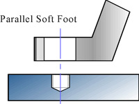 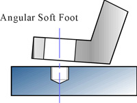
Parallel Soft Foot Angular Soft Foot
How to check for Soft Foot
-
Move indicators to 12 o'clock position, depress indicators and then zero.
-
Loosen one base bolt. If indicator moves away form zero, place the amount of shims that will slide under that foot. Retighten bolt and make sure the dial indicator needle does not move.
-
Repeat this procedure for the remaining feet.
Step 10
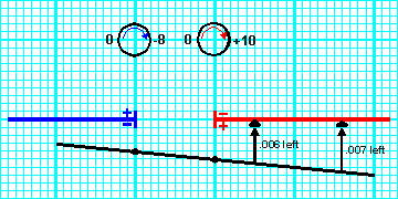
Perform Vertical Move
The vertical move is the part of the alignment process that aligns the two shaft's centerlines into their proper up and down position. Usually you will have to add or remove shims in this step. The indicators are zeroed on the top and read at the bottom. (start with a plus + reading if you need to compensate for sag)
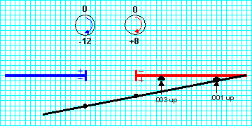
Example:
the indicator on the pump reads -12
the indicator on the motor reads +8
This means that the shafts are one half the total indicator reading from being collinear at these points.
Using a square grid graph paper to illustrate the position. Under the indicator position mark the point that is half the indicator reading. (-6 for pump side indicator and +4 for the motor side indicator) Connect these two points with a line and then continue the line past the lines representing the feet on the motor. The graph now shows that the front foot needs to have a .003" shim added and the back foot needs to have a .001" shim added.
Now with your shims in place. Tighten all bolts and take and check your readings. If the readings are within tolerance than your equipment should be aligned.
Step 11
Tighten all bolts and recheck indicator readings.
Step 12
Remove alignment brackets.
The more you become familiar with these steps the faster you will be able to align your machinery. |