Knowledge Base:  
Accelerometer Installation Guide
Last Updated: 05/02/2013
Field Application Note courtesy of STI Vibration Monitoring Inc. Please visit STI at www.stiweb.com.

Accelerometer Installation Guide

Table of Contents:

Section I:

  • Introduction

Section II:

  • Mounting Accessories
  • Installation Tools
  • Adhesives and Sealants

Section III:

  • Preferred Mounting Locations
  • Direct Mounting
  • Adhesive/Stud Mounting
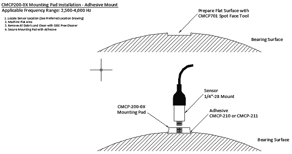
  • Adhesive Mounting
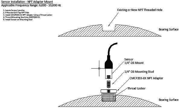
  • NPT Adapter Mounting
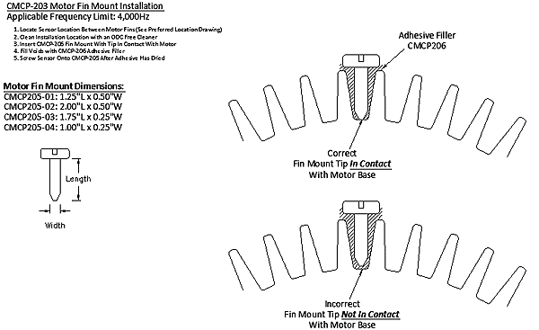
  • Motor Fin Mount

Section IV:

  • Cabling
  • Signal Interference Sources
  • Sensor Wiring


Section I:
Introduction:

There are three mounting methods typically used for vibration monitoring applications; stud mounting, adhesive bonding and magnetic mounting. Stud mounting is the preferred method for permanent mounting applications. This method is accomplished by securing the sensor directly to the bearing housing using a mounting stud. This method allows the sensor to measure vibration according to the manufacturer’s specifications. The mounting location for the accelerometer should be clean and paint free, also the mounting surface should be spot‐faced to a surface smoothness of 32 micro‐inches. The diameter of the spot‐face should be about 10% larger than the sensor diameter. Any irregularities in the mounting surface preparation will translate into improper measurements or damage to the sensor may occur. STI prefers that a mounting pad be placed between the machine and the sensor to provide a smooth surface for the accelerometer to attach to.

Adhesive or glue mounting provides a secure attachment without extensive machining; however this method will reduce the operational frequency range since the adhesive will act like a shock absorber, this is also known as damping. The replacement or removal of the sensor is also more difficult than any other mounting method. The most important issue for using adhesives is surface cleanliness, without a clean surface the adhesive will not fully bond to the machine.

The magnetic mounting method is typically used for temporary measurements with a portable data collector or analyzer. This method is not recommended for permanent monitoring. The sensor may be inadvertently moved and the multiple surfaces and materials of the magnet may interfere with or increase high frequency signals.
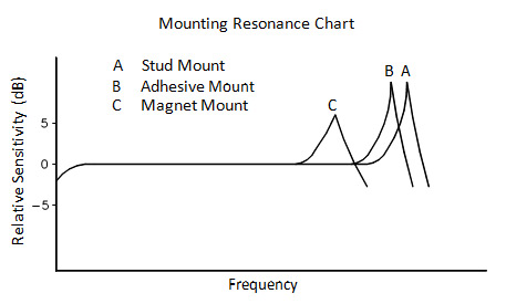
As can be seen in the figure below, the mounting method has an effect on the operating frequency range of an accelerometer. By design, accelerometers have a natural resonance which is 3 to 5 times higher than the advertised high end frequency response. The frequency response range is limited so that a flat response is provided over the operating range. The advertised range is achievable only by stud mounting. Any other mounting method will adversely affect the natural resonance, and in turn the usable frequency response range.

Mounting Resonance Chart.png
***STI’s preferred mounting method is the stud mount with mounting pad and epoxy.***


Section II:
Mounting Accessories:


Part Number:

Description:

Use:


CMCP‐200 Series
CMCP‐200‐01
CMCP‐200‐02

Accelerometer Mounting Pads
1/4” x 1” Dia.
3/8” x 1” Dia.

Provides Ideal Mounting Surface. Use 1/4” pad for stud/adhesive mounting and 3/8” pad for adhesive mounting.

cmcp200 Accelerometer Mounting Pads

CMCP‐203 Series
CMCP‐203‐01
CMCP‐203‐02
CMCP‐203‐03
CMCP‐203‐04

Pipe Thread Mounting Adapter
1/2” NPT
3/4” NPT
3/8” NPT
1/4” NPT

Makes use of existing NPT threaded holes to mount sensors. Adapters are finished with a lapped surface and a 1/4”‐28 threaded hole.

CMCP203 Pipe Thread Mounting Adapter

CMCP‐205 Series
CMCP‐205‐01
CMCP‐205‐02
CMCP‐205‐03
CMCP‐205‐04

Motor Fin Mounts
1.25” L x 0.50” W
2.00” L x 0.50” W
1.75” L x 0.25” W
1.00” L x 025” W

Allows for mounting sensors in
between motor fins when a flat surface is not available. Tips are angled to ensure contact with machine casing.

Motor Fin Mounts

CMCP‐230 Series
CMCP‐230‐01
CMCP‐230‐02
CMCP‐230‐03

1/4”‐28 UNF Mounting Studs
1/2” in Length
3/4” in Length
3/8” in Length

Sold in packs of 10.

CMCP230 1/4”-28 UNF Mounting Studs

Installation Tools:

Part Number

Description

Use:


CMCP‐270

Piloted End Mill

Used to mill a 1” flat surface and also provides a guide hole for tapping Ό”‐ 28 threads. Includes end mill, pilot, drill bit and Allen wrench

cmcp270 Piloted End Mill

CMCP‐271

Piloted End Mill with
Replaceable Cutting Tips

Same as CMCP‐270 but provides replaceable cutting tips. Cost effective when mounting a large quantity of sensors.

Accelerometer Mounting: Indexable Counterbore Kit with Replaceable Blades

Adhesives and Sealants:

Part Number

Description

Use:


CMCP‐206

Adhesive Filler

Used to fill voids when installing
CMCP‐205 motor fin mounts. 2 Part Epoxy

cmcp206 Adhesive Filler

CMCP‐207

Adhesive Dispenser

Used to dispense CMCP‐206 Adhesive Filler

cmcp207 Adhesive Dispenser

CMCP‐208

Mixing Nozzle

Used to mix CMCP‐206 two part
epoxy

cmcp208 Mixing Nozzle

CMCP‐210

Acrylic Adhesive Bypacs

2 Part Epoxy for easier mounting of 1 or 2 sensors

cmcp210 Acrylic Adhesive Bypacs

CMCP‐211

Depend 330 and Activator

2 Part Adhesive with spray activator. Good for over 10 installations

cmcp211Depend 330 and Activator

CMCP‐212

Silicone Dielectric

Helps ensure transmittal of higher frequencies

cmcp212 Silicone Dielectric

CMCP‐213

Silicone Sealant

Used to “flood” connectors to
eliminate moisture build up inside of sensor connector

cmcp213 Silicone Sealant


Section III:
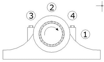
Preferred Mounting Locations:

Preferred Mounting Locations.png

Preferred Mounting Locations


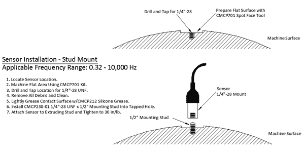
Direct Stud Mount:


Direct Stud Mount.png


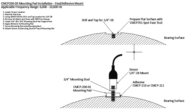
Mounting Pad Mount w/Adhesive: (Preferred)


MP and Stud Mount.png


Mounting Pad with Adhesive Mount:


MP Adhesive Mount.png


NPT Adapter Mount:


NPT Mount.png


Motor Fin Mount:


Motor Fin Mount.png


Section IV: Cabling:

The instrument wire from the vibration sensor to its transmitter or monitor should be either a twisted pair or triad cable depending on the sensors requirement. These cables should be stranded, twisted, individually insulated, shielded and with an overall jacket. The shields or drain wires must be insulated or isolated from each other and the conduit. The use of multi‐conductor cable with a single shield is not suggested due to its susceptibility to induced noise and line interference.


The gauge or thickness of the instrument wire is determined by the distance between the sensor and the transmitter or monitor. Long lengths of cable will deteriorate the signal; this can be a problem when monitoring gear mesh frequencies, blade pass frequencies or rolling element bearing frequencies.

Signal Interference Sources:

Noise or Line Interference can be induced in a Vibration Monitoring System in a number of ways. However, there must first exist a source for the induced noise. There are numerous noise sources available in an industrial or power generation plant:

•      AC Power Transients
•      Ground Differentials
•      Switching Circuits
•      High Voltage Circuits
•      Improper Load Balance

Noise can be induced in a Vibration Monitoring System through Electrostatic (Capacitive), Electromagnetic (Inductive) or Conductive Coupling (Direct Connection). All noise will be induced in the monitoring system through one or more of its external connections or Field Wiring.


It is critical that conduit be utilized with the sensor cabling and its associated wiring. The use of conduit greatly reduces the possibility of induced noise or line interference on the signals path. The conduit system shall be dedicated to the monitoring system and no other wiring should be in the same conduit. Also, cable trays, wire ways, or instrument trays are an unacceptable alternative to dedicated conduit. Route the conduit as far as
possible from any power cables, relay contact cables and motor control cables. If you must cross these cables do so at a 90° angle.

The following table offers a guideline to determine the maximum cable length for different types of sensors. This is based on an ideal installation where the cable is properly grounded and installed in a dedicated conduit system.

Sensor Sensitivity

Maximum Cable Length

100mV/g

100‐150’

500mV/g

150‐500’

4‐20mA Velocity Sensors

>1000’


Sensor Wiring:

A “Single Point Grounding” scheme must be utilized when installing a vibration monitoring system. All grounds must be connected at one location. It is recommended that the grounding point be at the transmitter/monitor end and not at the machine. On most machines or where other machines are being monitored significant ground differentials can be found between sensor locations and machines.

All Instrument Wire shields must be grounded at one end of the cable, and the other end left floating or not connected. The Instrument Wire should be grounded at the Vibration Monitoring System. If the shield is not grounded, the shield will become an antenna increasing induced noise on the signal path. If the shield is grounded at both ends, it will allow ground current (ground loop noise) to flow through the shield, seriously increasing signal noise.


Sensors with Built In Cables:

Cable Part Number

Description

Color Code

CMCP1100‐XX
CMCP1100S-XX

Low Cost Accelerometer with Integral Cable

Red (+)
Black (‐) Shield/Drain

CMCP1100HT‐XX

High Temperature Low Cost Accelerometer with Integral Cable

White (+)
Black (‐) Shield/Drain

Extension Cables:

Cable Part Number

Description

Color Code

CMCP602L‐XX‐XX

Accelerometer Extension Cable
2 Pin, Standard Cable

Red (A)
Black (B) Shield/Drain

CMCP602H‐XX‐XX

Accelerometer Extension Cable
2 Pin, High Temperature Cable

White (A)
Black (B) Shield/Drain

CMCP603L‐XX‐XX
CMCP603H-XX-XX

Accelerometer Extension Cable
3 Pin.

Red (A)
Black (B) White(C) Shield/Drain


Was this article helpful?

Comments:
 

Related Articles
 > Dial Indicator Alignment
 > CMCP1100 Wiring Diagram
 > Field Application Note: Reverse Dial Alignment
 > Acceleration Enveloping
 > Accelerometer Transducers and Installation
 > Balancing
 > Bearing Failure Modes
 > Classification of Machines
 > Comparing Vibration Readings
 > Conventions
 > Cooling Tower Fans
 > Differential / Rotor Expansion
 > Eccentricity
 > Eddy Current (Proximity Probe) Transducer Installation: Part 1 Radial Vibration
 > Fault Detection / OK Circuits
 > Field Service
 > Field Wiring
 > Frequency Domain
 > Journal Bearings
 > Machine Classifications
 > Maintenance Methods
 > Monitoring System Users
 > Piping Vibration
 > PM Program Part 2: Routes
 > Predictive Maintenance Program (PMP)
 > Reciprocating Compressors
 > Reverse Dial Alignment
 > System Response
 > Thrust Position
 > Transient Analysis
 > Turbine Supervisory Instrumentation
 > Turbine Supervisory Instrumentation 1
 > Turbine Supervisory Instrumentation: Shell or Case Expansion
 > Valve Expansion
 > Velocity Transducer Installation
 > ISO 10816 Vibration Severity Chart
 > Interpretation of the International Standard ISO 10816-3