|
|
|
Flatness Measurement Last Updated: 07/16/2012 |
|
Application Note Courtesy of Damalini Flatness Flatness measurement is done on for example machine tables, wire parties in paper making machines, flanges (circular planes), machine foundations etc. Flatness measurement with a reference plane that "rests" on three ref. points The laser beam is adjusted to pass through 3 selected ref. points at the same distance from the measurement object. The measurement values at the reference points are leveled to zero. The measurement values at the other points will show the deviation from the laser plane.
Flatness measurement with a reference plane parallel to the horizontal plane The laser beam is leveled according to the vials (laser transmitter D22) and the measurement value at the first point is leveled to zero. The measurement values at the other points will show the deviation from the horizontal plane.
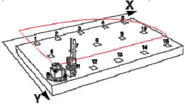
Points on the surface to be measured When measuring flatness it is important to decide which points on the surface to be measured. The measurement points shall be marked in a coordinate system in X- and Y-direction. Up to 300 measurement points can be handled by the Easy-Laser® system. All flatness measurements are based on the use of 3 reference points that our "laser plane" will rest on. The values we then will get at each measurement position are compared to this plane. The measurement values can be recalculated so that any 3 of them become zero references, with the limitation that only 2 of them are in line horizontally, vertically or diagonally, in the coordinate system.
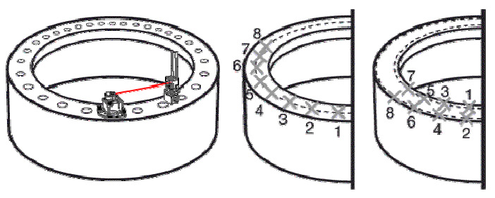
Measuring flatness/twist on circular planes Measuring flatness/twist on circular planes, for example on flanges, is based on the use of three reference points placed at 120° pitch on the circle. Decide the number of measurement points and which three should be reference points at which the laser plane rests. All measurement points are now compared to this plane. It is possible to measure both inner and outer circle of the flange (ID / OD), with up to 300 points. The measurements are taken as shown in the picture below. You can then display the graph in the EasyLink program (Version 2.2).
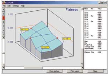
Flatness measurement (EasyLink).
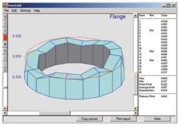
Measuring flatness on circular planes (EasyLink). |