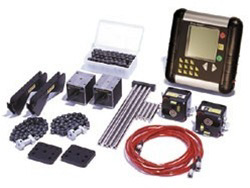
Traditionally, maintenance departments do not sing their own praises. Maybe that should change? In many companies the maintenance departments are still considered to be a necessary expense instead of a profit center. This perception is starting to change as improved maintenance procedures demonstrate cost savings that go directly to the companys bottom line by reducing the energy costs and improving reliability. One example is Lake Erie Steel, a large steel mill in Nanticoke Ontario, who recently purchased an Easy-Laser®, dual beam, shaft alignment system. This system gives them the ability to align the 14 foot long Jack Shafts on their water cooling towers. Spanning the 14 feet coupling to coupling is not a problem for the Easy-Laser® that is capable of shaft alignment over a distance of sixty feet. In the past a contractor had done this work using a single beam system that could not span the required distance of fifteen feet from the motor to gearbox. The procedure for this type of system had been to measure alignment at each coupling on either end of the Jack Shaft and then use both sets of alignment results to calculate the necessary correction in order to align the machine units.
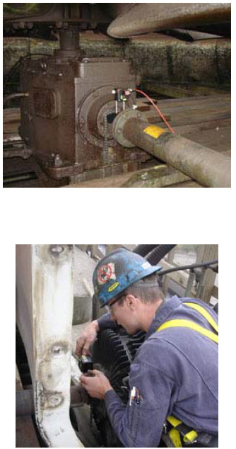
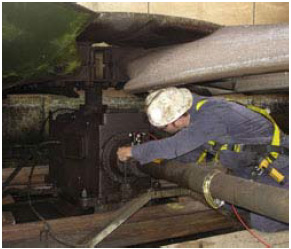
With the Easy-Laser®, Lake Eries Industrial Mechanic Cliff Dosser, and his crew of apprentices and Coop Students, who work in the Hot Strip Mill Pump Zone, were now able to start the alignment of a jack shaft by mounting one laser/detector on the motor shaft and the other on the gearbox shaft there-by doing true shaft to shaft alignment that was not possible previously. Then by simply using the laser beams which were centered in the closed target at the 9 oclock position the shaft was then rotated to the 3 oclock position. This is a very quick and easy procedure that is used when doing rough alignment for jack shafts. It determines immediately if the machine is out of alignment and the proper movements for correction. In this case it showed that the alignment was grossly out so corrective action began.
Now with the laser target doors open, measurements were recorded in as little as forty degrees of shaft rotation. The display showed real time readings in both the horizontal and vertical planes for the moveable machine. The moveable machine is usually the motor however it is possible to change the configuration of the machine in the laser display if the driven (Gearbox) unit is to be moved or even a combination of different machine feet. The trick is in choosing the correction that requires the least amount of movement. Now all that was needed was to reposition the machine but the real skill was in controlling the movement. At a distance of fifteen feet you dont bump anything; its a gradual move which is best done with jacking bolts. The work was completed and unit was put back in service. Cliff took an initial amperage reading on the unit before the re-alignment and it was found to be 174 amps. After the work was completed another reading was taken showing 155 amps. Thats a whopping 19 amp drop!
Although Lake Erie Steel is running almost 24/7 it was estimated that the cooling tower ran half the year as it is not
required in the winter months. That equates to 4,380 running hours so a 19 amp drop works out to a little over 10% in energy reduction which would be 78,735 Kilowatt hours saved. Using the average of 0.07 cents per KW, a savings of $5,511.44 per year is realized.
WOW! I think Cliff and his crew should be quite pleased with themselves
as they look at their success in yet another way. They have not only
reduced the plants overall carbon footprint by reducing energy that
relates to 54 metric tons of CO2, or the equivalent of 8.2 cars off the
road, but they have also done an excellent job of re-aligning the motor
and gearbox which means that, barring unforeseen circumstances, the
plant will get the optimum life out of the cooling tower drive. Id say
that was a good days work wouldnt you?