This application note provides a set of
conventions to provide order and meaning to how transducers relate to their mounting and
the machine.
Motion Towards
Vibration transducers measure all vibration they sense regardless of the direction of the
mechanical vibration. The displayed output of a transducer will resemble a sinusoidal wave
pattern, with some portion of the signal above (or on the positive side) the zero
reference and some portion below ( or on the negative side) the zero reference.
A common convention employed in the design and construction of all transducers is that
motion towards the transducer will cause a positive signal output. This convention allows
the analyst to determine how the rotor or bearing case is moving in relationship to the
sensor. This information is vital when determining phase relationships between various
sensors and between the rotor and its case.
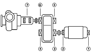
Bearing Number
 Distinguishing one bearing from another is an important consideration when installing or
analyzing several bearings on a machine train. A common convention is to start numbering
the bearings starting from the driver end. The choice of whether to use numbers or letters
is immaterial, the sequence should increase as additional bearings are added to the
diagram. Distinguishing one bearing from another is an important consideration when installing or
analyzing several bearings on a machine train. A common convention is to start numbering
the bearings starting from the driver end. The choice of whether to use numbers or letters
is immaterial, the sequence should increase as additional bearings are added to the
diagram.
Machine trains with gear increasers may cause some confusion when the gear is
considered. When numbering a gear, continue numbering the bearings along the gear shaft
instead of around the gear casing.
X & Y
When two transducers are installed in a single plane, such as two Eddy Current sensors on
one bearing, they have a relationship to each other which must have a standard
specification. Defining their orientation and relationship to each other requires
understanding how an oscilloscope operates. The oscilloscope was the first, and still is,
a basic analysis instrument.
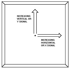
A dual channel oscilloscope allows viewing the
output signals from two different sensors simultaneously on a cathode ray tube (CRT). When
the oscilloscope is in the XY, or cartesian mode, the center of the screen represents zero
output from both sensors. This operational mode is sometimes called orbit mode. As the
signal from the horizontal sensor increases (in the positive direction) the dot, or trace
on the display moves to the right. An increasing signal in the vertical plane causes the
trace to move up on the display. Thus, following standard cartesian notation, the positive
X (horizontal) input is to the left of the positive Y (vertical) input.
 Two
sensors must be installed 90 from each other to measure the entire amount of vibration in
two planes (vertical and horizontal). Two
sensors must be installed 90 from each other to measure the entire amount of vibration in
two planes (vertical and horizontal).
This requirement stems from the fact that each sensor is designed to measure vibration
only along the sensor's axis. If the sensors are not installed at a 90 orientation, one of
the sensors will be measuring some of the vibration which is being measured by the other,
which can only confuse any analysis.
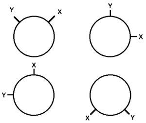
To
distinguish one sensor from the other they are labeled X and Y.
Determining which is X and which is Y requires using the bearing number convention
discussed earlier (viewing the sensors from the driver end) and utilizing standard
oscilloscope orientation. Within the 90 orientation the X sensor is located to the left of
the Y sensor when the sensors are mounted above the horizontal split line of the bearing.
Should the sensors be oriented at a different location on the bearing, simply imagine the
sensors located above the horizontal and follow the stated orientation convention. This
convention applies regardless of shaft rotation direction. 
Transducer Conventions Checklist
- Motion Towards
- Bearing Number
- X & Y
|

