Transient analysis is the study of how various
signals change during a machine's process or load change. This analysis is particularly
important during a machine's startup or shutdown when critical speeds or natural
resonances are encountered. Observing the overall amplitudes or individual spectra will
not be sufficient to document how the entire machine behaves during transient conditions.
Data collection modes fall into two general categories: observing transducer output
signals with respect to machine speed and observing transducer output signals with respect
to time. Sometimes, a combination of the two modes may be required.
BODÉ PLOT

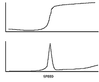
A Bodé, pronounced bow-day, plot is a display of three variables: signal
amplitude, machine speed, and phase angle. The three variables are usually synchronized to
the machine operating speed, but occasionally may be synchronized to some multiple of
machine speed depending upon the type of machine fault being investigated.
The Bodé plot is essentially two displays: phase angle versus machine speed and
amplitude versus machine speed. Analysis of the plot can determine at what speed(s) a
critical speed exists, the amount of runout associated with a Non-Contact PickUp (NCPU),
the balance condition, system damping, and the operating phase angle and amplitude at
various machine speed.
POLAR PLOT

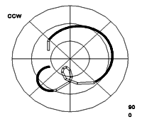
The polar, or nyquist, plot is also a plot containing the same three variables as a Bodé
plot. The variables are plotted on a single circular chart instead of
two separate plots.
The center of the plot represents zero speed and
zero amplitude with subsequent amplitude and phase angle measurements plotted with their
associated machine speed. Phase angle measurements are plotted around the circumference of
the chart, against machine rotation direction. Polar plots are always filtered to machine
running speed or some multiple of the machine speed, depending upon the fault being
investigated.
Machine critical speeds and natural resonances are displayed as loops,
with the critical speed situated 90 from the start of the loop. This characteristic makes
identification of resonances and critical speeds easy. Other information available from
the plot are: slow speed runout associated with NCPUs, system damping, balance condition,
and operating phase angle and amplitude at various machine speeds.
CASCADE PLOT
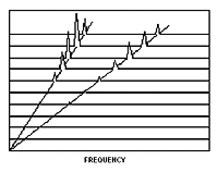
Cascade
or Waterfall plots, also have three displayed variables: amplitude, frequency, and machine
speed. This display differs from the other transient plots because it is essentially a
collection of spectra. Each spectrum is associated with a specific machine operating
speed. Setting the maximum frequency (Fmax) and the spectrum resolution are important for
accurate diagnosis. See the Application Note, Diagnostic Techniques-Part 2, Frequency
Domain for further discussion of these settings.
Transient Analysis Checklist
- Bodé Plot
- Polar Plot
- Cascade Plot
|

