 Cooling Tower Fans have
applications in all industries. They remove heat from other materials, usually water. A
cooling tower may consist of one cell or many individual cells in a single
structure. A single plant may have multiple structures. Cooling Tower Fans come in two
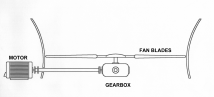
basic types. The first type has the motor mounted to the side of the cell and uses a
jackshaft to drive the gearbox in the center. The second type has both the motor and
gearbox centrally mounted in the cell. The mechanical components of a Cooling Tower Fan
are made up of, Motor, Jackshaft (Optional), Gearbox, and Fan Blades. Cooling Tower Fans have
applications in all industries. They remove heat from other materials, usually water. A
cooling tower may consist of one cell or many individual cells in a single
structure. A single plant may have multiple structures. Cooling Tower Fans come in two
basic types. The first type has the motor mounted to the side of the cell and uses a
jackshaft to drive the gearbox in the center. The second type has both the motor and
gearbox centrally mounted in the cell. The mechanical components of a Cooling Tower Fan
are made up of, Motor, Jackshaft (Optional), Gearbox, and Fan Blades.
The motor speed for a Cooling Tower
Fan is usually 1800 RPM. Fan speeds are much slower and determined by the diameter of the
blades to keep the blade tips subsonic. Average cells are 14 feet to 28 feet in diameter.
Fan speeds of 90 to 230 RPM are normal for cooling tower fans. In cooler climates, the
fans can be reversing to prevent freeze during the winter.
The most common Cooling Tower Fan
failure involves the gearbox or fan blades and are catastrophic in nature. In many cases,
this type of failure leaves the gearbox and fan blades lying in the cooling water pond at
the bottom of the tower.
Many Cooling Tower Fans were equipped by the OEM (Original Equipment
Manufacture) with a earthquake detection type devices mounted close to the cell.
Although questionable to start with for this application, over time most of these devices
have quit working due to corrosion or neglect.
Permanent monitoring is the recommended solution for preventing cooling
tower cell failures. Periodic measurement programs rarely produce the desired result. In
most cases, the location and environment discourages any attempts to take data or visually
inspect the fan.
Permanent monitoring of a cooling tower fan cell requires direct
monitoring of the most important component by mounting a transducer directly on the
gearbox. Additional system protection can be added by mounting transducer(s) to the motor.
Additionally, knowledge of the expected vibration frequencies is important.
1. Fan Speed 90-300 RPM
2. Blade Pass (Fan Speed X # of Blades)
3. Gear Mesh Frequencies
4. Motor Speed
5. Bearing Frequencies
Gear Vibration
The central component of a cooling tower is the gearbox. This is often
a high maintenance source due to aerodynamic loading from the fan, excessive loading on
the gear teeth, and improper alignment of the gear to the motor.
The gearbox is always located within the cooling water stream requiring
special consideration for mounting a vibration sensor. The environment is usually caustic
due to chemicals added to control the pH level of the cooling water.
A vibration sensor must be able to measure the expected gear mesh
frequency, blade passage, and bearing defect frequencies. Other frequencies of interest
include fan balance and motor alignment.
Gear and bearing defect frequencies tend to be the highest frequencies,
while the fan balance frequencies are the lowest to be monitored. The other frequencies
are found scattered between these extremes.
Monitoring the gearbox can be accomplished by installing a single low
frequency accelerometer (CMCPWIL793V) on the gearbox in a horizontal orientation
perpendicular to the jackshaft. The output signal should be routed to CMCP500 Series
Monitors. One monitor should be specified to measure velocity for higher frequencies like
gear mesh. The second monitor should be specified to integrate the signal to displacement
terms for lower frequencies such as blade speed and blade pass.
(1) CMCPWIL793V Accelerometer 100mV/In/Sec Output.
(1) CMCP602L-32-01-02-01 Armored Extension Cable.
(1) CMCP200-01 Mounting Pad 1/4"
(1) CMCP230 Mounting Stud
(1) CMCP220 Acrylic Adhesive Bypac
(1) CMCP530-100V-02P-00-00 Velocity Monitor
(1) CMCP535-100V-30-00-00 Displacement Monitor
Motor Vibration
Motor vibration frequencies of interest include motor unbalance, rotor
bar defects, output shaft alignment, and bearing defect frequencies. A complete continuous
monitoring approach should include one accelerometer per bearing location. Mounting
orientation for the accelerometers should be horizontal at the bearing. As the motor speed
is usually 1800 RPM economical standard accelerometers such as the STI CMCP1200 can be
used. A more economical approach would be to mount a single accelerometer at the motor
output shaft bearing location only.
(2) CMCP1200 Industrial Accelerometer
(2) CMCP602L-16-01-02-01 Armored Extension Cable
(2) CMCP200-01 Mounting Pad 1/4"
(2) CMCP230 Mounting Stud
(2) CMCP220 Acrylic Adhesive Bypacs
(2) CMCP530-100A-02P-00-00 Velocity Monitor
Start Up Considerations
All CMCP500 Series Monitors are provided with relays, reset terminals
and a trip multiply function. Cooling Tower Fans experience large amounts of vibration
during start-up. Either timer logic or a contact to energize trip multiply needs to be
provided if the monitors are wired to shutdown.
DCS/PLC Systems
The CMCP500 series monitors can be equipped with Modbus or TCP/IP
communications. I/O can be specified to provide operators with vibration levels, alarm set
points, discrete alarms and the ability to energize the trip multiply and reset functions.
A complete system using Modbus or TCP/IP can be specified providing operators with screens
and software. |