|
|
|
Eddy Current (Proximity Probe) Transducer Installation: Part 1 Radial Vibration Last Updated: 12/30/2011 |
|||||||||||||||||||||||||||||
 Eddy Current (Proximity Probe)
|
| Eddy Current Transducers (Proximity Probes) are
the vibration transducer of choice when installing vibration monitoring on Journal Bearing
equipped rotating machinery. Eddy Current Transducers are the only transducers that
provide Shaft Relative (shaft relative to the bearing) vibration measurement.
Several methods are usually available for the installation of Eddy Current Transducers, including internal, internal/external, and external mounting. Before selecting the appropriate method of mounting Eddy Current Transducers, special consideration needs to be given to several important installation considerations that will determine the success of your monitoring program. Theory of Operation
Special ConsiderationsNumber of TransducersAll vibration transducers measure motion in their mounted plane. In other words, shaft motion either directly away from or towards the mounted Eddy Current Probe will be measured as radial vibration.On smaller less critical machines, one (1) Eddy Current Transducer system per bearing may be adequate for machine protection. The single Eddy Current Probe will then measure the shaft's vibration in that given plane. Therefore, the Eddy Current Probe should be mounted in the plane where the greatest vibration is expected. On larger more critical machines, two (2) Eddy Current Transducer systems are normally recommended per bearing. The Probes for this type of installation should be mounted 900 apart from each other. Since the Probes will measure the vibration in their respective planes, the shaft's total vibration within the journal bearing is measured. An "Orbit" or cartesian product of the two vibration signals may be viewed when both Eddy Current Transducers are connected to an SKF-CM Information System or an Oscilloscope. Linear RangeSeveral versions of Eddy Current Transducers are available with a variety of Linear Ranges and body styles. In most cases, SKF-CM's CMSS68 with a linear range of 90 mils (0.090") is more than adequate for Radial Vibration measurements...
Target Material/Target AreaTarget Material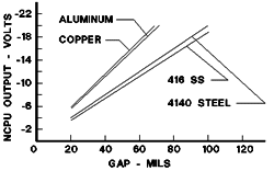 Eddy Current Transducers are calibrated at the factory for 4140 Steel unless specified otherwise.
As Eddy Currents are sensitive to the permeability and resistivity of the shaft material
any shaft material other than 4000 series steels must be specified at the time of order.
In cases of exotic shaft material a sample may need to be supplied to the factory. Eddy Current Transducers are calibrated at the factory for 4140 Steel unless specified otherwise.
As Eddy Currents are sensitive to the permeability and resistivity of the shaft material
any shaft material other than 4000 series steels must be specified at the time of order.
In cases of exotic shaft material a sample may need to be supplied to the factory.
Mechanical RunoutEddy Current Transducers are also sensitive to the shaft smoothness for Radial Vibration. A smooth (64 micro-inch) area approximately 3 times the diameter of the Probe must be provided for a viewing area. The prepared journal area on most shafts are wider than the bearing itself allowing for Probe installation immediately adjacent to the bearing. Electrical RunoutSince Eddy Current Transducers are sensitive to the permeability and resistivity of the target material and the field of the transducer extends into the surface area of the shaft by approximately 15 mils (0.015"), care must be taken to avoid non homogeneous viewing area materials such as Chrome. Another form of electrical runout can be caused by small magnetic fields such as those left by Magna-fluxing without proper degaussing. Perpendicular to shaft centerlineCare must be exercised in all installations to insure that the Eddy Current probes are mounted perpendicular to the shaft center-line. Deviation by more than 1-2 degrees will effect the output sensitivity of the system. Orientation of Transducer(s)As most machine casings are horizontally split, transducers are commonly found mounted at 450 both sides of vertical 900 apart. If possible transducer orientation should be consistent along the length of the machine train for easier machine diagnostics. In all cases orientation should be well documented. Transducer (Probe) side clearances Eddy Current Probe tip to tip clearancesAlthough Probe tip to tip clearances are not normally an issue on most machines, it should be noted that Eddy Current Probes radiate an RF Field larger than the Probe tip itself. As an example, Model CMSS65 and 68 probe should never be installed with less than one (1) inch of Probe tip to tip clearance. Larger Probes require more clearance. Failure to follow this rule will allow the Oscillator/Demodulator to create a "beat" frequency which will be the sum and difference of the two Oscillator/Demodulator RF frequencies. System Cable Length and Junction BoxesEddy Current Transducer Systems are a "tuned" length, and several system lengths are available. Length is measured from the Probe tip to the Oscillator/Demodulator, and is measured electrically which can slightly vary the physical length. For example, the Model CMSS65 and 68 are available in 5 and 10 meter system lengths. Care must be taken to insure that the proper system length is ordered to reach the required Junction Box.
Instrument WireA 3-wire twisted shielded instrument wire (ie; Belden #8770) is used to connect each Oscillator/Demodulator to the Signal Conditioner in the Monitor. Where possible, a single run of wire from the Oscillator/Demodulator (Junction Box) to the Monitor location should be used. Splices should be avoided. The gauge of the selected wire depends on the length of the instrument wire run, and should be as follows to prevent loss of high frequency signal:
The following wiring connection convention should be followed:
Common Point GroundingTo prevent Ground Loops from creating system noise, system common, ground and instrument wire shield must be connected to ground at one location only. In most cases, the recommendation is to connect commons, grounds and shields at the Monitor location. This means that all commons, grounds and shields must be floated or not connected at the machine. Occasionally due to installation methods instrument wire shields are connected to ground at the machine case and not at the monitor. In this case, all of the instrument wire shields must be floated or not connected at the monitor. ConduitDedicated conduit should be provided in all installations for both mechanical and noise protection. Flexible metal conduit should be used from the Eddy Probe to the Oscillator /Demodulator junction box, and rigid bonded metal conduit from the junction box to the monitor. CalibrationAll Eddy Current Systems (Probe, Cable and Oscillator Demodulator) should be calibrated prior to being installed. This can be done by using a SKF-CM CMSS601 Static Calibrator, -24 VDC Power Supply and a Digital Volt Meter. The Probe is installed in the tester with the target set against the Probe tip. The micrometer with target attached is then rotated away from the Probe in 0.005" or 5 mil increments. The voltage reading is recorded and graphed at each increment. The CMSS601 Calibrator will produce a voltage change of 1.0 VDC +-0.05 VDC for each 5 mils of gap change while the target is within the Systems linear range. GapWhen installed,Eddy Current Probes must be gapped properly. In most Radial Vibration applications, gapping the transducer to the center of the linear range is adequate. For the Model CMSS65 and 68 gap should be set for -12.0 VDC using a Digital Volt Meter (DVM), this corresponds to an approximate mechanical gap of 0.060" or 60 mils. The voltage method of gapping the Probe is recommended over mechanical gapping. In all cases, final Probe gap voltage should be documented and kept in a safe place. Internal Mounting
Provisions must be made for the transducer's cable exiting the bearing housing. This can be accomplished by using an existing plug or fitting, or by drilling and tapping a hole above the oil line. The Transducer's cables must also be tied down within the bearing housing to prevent cable failure from "windage". For added safety and reliability, all fasteners inside the bearing housing should be safety wired, or otherwise prevented from working loose inside the machine. Advantages of Internal Mounting
Disadvantages of Internal Mounting
External/Internal Mounting
In some cases due to space limitations External/Internal mounting is accomplished by drilling or making use of existing holes in the bearing itself, usually penetrating at a oil return groove.
Advantages of External/Internal Mounting
Disadvantages of External/Internal Mounting
External Mounting
Advantages of External Mounting
Disadvantages of External Mounting
Installation Checklist
|
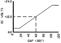 Eddy Current Transducers work on the proximity theory of operation. A Eddy Current System
consists of a matched component system: a Probe, an Extension Cable and an
Oscillator /Demodulator. A high frequency RF signal @2 mHZ is generated by the
Oscillator/Demodulator, sent through the extension cable and radiated from the Probe tip.
Eddy currents are generated in the surface of the shaft. The Oscillator /Demodulator
demodulates the signal and provides a modulated DC Voltage where the DC portion is
directly proportional to gap (distance) and the AC portion is directly proportional to
vibration. In this way, a Eddy Current Transducer can be used for both Radial Vibration
and distance measurements such as Thrust Position and Shaft Position.
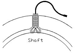
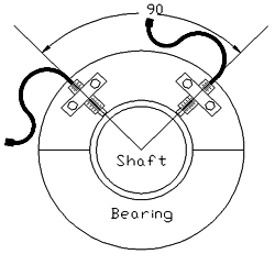 Internal Mounting is accomplished with the Eddy Current Probes mounted
internally to the machine or bearing housing with a CMCP805 Bracket or with a custom designed and
manufactured bracket. The Transducer system must be installed and gapped properly prior to
the bearing cover being reinstalled.
 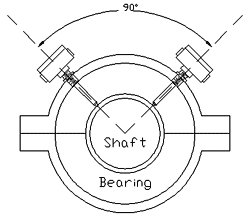 External/Internal mounting is accomplished when the Eddy Probes are mounted with a
Mounting Adapter (CMCP801). These adopters allow external access
to the Probe yet allows the Probe tip to be internal to the machine or bearing housing.
Care must be taken in drilling and tapping the bearing housing or cover to insure that the
Eddy Probes will be perpendicular to the shaft center line.
 Pure external Eddy Probe mounting is usually a last resort installation. The only valid
reason for using this method is inadequate space available within
the bearing housing for internal mounting. Special care must be given to the Eddy Probe
viewing area and mechanical protection of the transducer and cable.