Over the years, two methods of vibration transducer
fault detection have become prominent: OK Circuits
and Fault Detection Circuits. The objective of both
types of fault detection is to disable a vibration
monitoring system's ability to produce alarms or
shutdown a piece of rotating machinery when the
transducer systems integrity is in doubt.
It is important for the engineer responsible for the
installation and set-up of a vibration monitoring
system to fully understand how Fault Detection and
OK Circuits function. This insures that the system's
credibility is not damaged from false alarms and false
machinery trips.
Fault Detection Circuits
IRD Mechanalysis developed Fault Detection
Circuitry for Case Mounted Transducers such as
Accelerometers and Velocity Pick-ups. IRD now uses
Fault Detection Circuits for all types of vibration
transducers in all permanently installed monitoring
systems. Fault Detection Circuits have an early
foundation in the instrument industry and have an
excellent record of reliability.
Theory of Operation
The theory of operation behind Fault Detection
Circuits is that all vibration transducers whether
Accelerometers, Velocity Pick-ups or Non Contacting
Pick-ups (NCPU's) have a minimum and maximum
vibration signal output while a machine is running.
IRD Mechanalysis provides two (2) levels (Low and
High) of fault detection in all monitoring systems.
These levels are programmed or set at time of
installation to best suit each installation's needs.
Field Application Note
Fault Detection Circuits/OK Circuits FDC
In some cases, only low level fault alarms are
programmed as the possibility of very high vibration
levels exist.
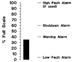
As an example, a rolling element bearing machine
rotating at 3600 RPM may have a scale of 0-1 in/sec,
with warning and alarm set at 0.2 and 0.3 in/sec
respectively. The lower fault alarm may be
programmed at 4 to 8% of Full Scale or 0.04 to 0.08
in/sec. The high fault alarm, if used, may be set at 1
in/sec. As the machine normally vibrates in the 0.1 to
0.2 in/sec range no fault alarm exists unless there
has been a failure with the vibration transducer or
associated instrument wiring.
As the signal will drop below the low fault alarm when
the machine is shut down, IRD has equipped all
monitoring systems with a Machine On/Off Contact.
This is used to signal the monitor that the machine is
no longer running and to disable all alarms. In IRD's
more advanced monitors such as the 5915, the On/
Off Contact will also signal the monitor to suspend
such tasks as trending and spectrum gathering while
the machine is not running.
Another advantage of Machine On/Off Contacts is
that start up attenuation is automatically triggered,
and vibration signals can be attenuated by a factor of
three (3) during the start-up time programmed. This
allows a machine to reach a steady state running
speed, and pass through it's critical speeds before
alarms reach full value.
Advantages
Works with all types of vibration transducers.
Levels are programmed for each installation.
Monitors the transducer vibration signal output.
Disadvantages
Designed for Velocity and Acceleration transducers.
Does not monitor NCPU Gap.
Machine On/Off Contact required to prevent false
fault alarm when machine is shutdown.
OK Circuits
The OK Circuit was developed specifically for the
Non- Contacting Pick-up (NCPU) or Proximity Probe
Systems used in Sleeve Bearing-Radial Vibration
applications. It was then applied to other types of
transducers by some vibration system manufactures.
Theory of Operation
The theory of operation behind OK Circuits is that the
NCPU or Proximity System has a fixed linear range
with associated minimum and maximum DC Voltage
Gaps. If the DC Gap is outside of the permissible
range, then the transducer is no longer within it's
linear range and the output is suspect.
As Sleeve type bearings limit the total relative motion
between the shaft and bearing, OK Circuits work well
for Non-Contacting Pick-Ups installed for Radial
Vibration measurements.
In Thrust Position Installations, the OK Circuitry is not
allowed to disable the monitors ability to alarm and
shutdown, as severe thrust failure may cause the
thrust collar to travel outside of the range of the
NCPU transducer.
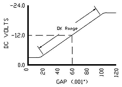
As an example, a standard proximity probe's linear
range is 80 mils or 0.080". The output sensitivity is
200 mV/mil. This relates to a total DC Voltage Range
of 16 VDC. If the center of the Linear range is -12
VDC then the useful range of the proximity
transducer is -4.0 VDC to -20.0 VDC.
Theory suggests that an open circuit will drive the DC
Voltage above -20.0 VDC, and a shorted circuit will
drive the voltage below -4.0 VDC. DC Voltage
Comparator circuits are used to monitor the existing
probe gap minimum (-4.0 VDC) and maximum (-20.0
VDC). If the DC Voltage is outside the selected
range, the monitor's ability to alarm or shutdown a
machine is disabled.
Other types of vibration transducers were adapted to
this circuitry by applying a DC bias voltage within the
OK Range through the transducer system. As the OK
Circuit was not specifically designed for other types
of transducers such as accelerometers and velocity
pick-ups, it will not detect failure of the transducer
itself but simply open or shorted wiring.
Advantages
- Works well for NCPU Sleeve Bearing-Radial
- Vibration Applications
- Works with the machine running or shutdown
Disadvantages
- Does not check the complete transducer system in
transducer types other than NCPU's.
- Only indicates if the NCPU transducer is gapped
properly, not if there is any vibration signal output.
- Cannot be used in Thrust Position applications as
thrust collar may move outside the NCPU linear
range during thrust failure.


