Balancing
Unbalance is a very common source of high
vibration that is identified by excessive levels of vibration amplitudes at a frequency
that is synchronous with machine speed. Possible sources for this malfunction may be
uneven product deposits around a fan or pump impeller, damaged or missing blades or vanes,
improper shaft component assembly, or any other uneven mass distribution around the rotor
axis. A machine that is operated within design conditions and is clean should not
experience severe unbalance vibration levels.
 Correction of unbalance situations
involves characterizing the heavy spot. The heavy spot is the radial location at which the
excessive radial mass distribution exists. This heavy spot is always a location which is opposite the location
where weight needs to be added. Unfortunately the location of the heavy spot cannot be
identified directly. However, we can identify the high spot location which is the point of
maximum displacement. The high spot is a radial location where the shaft experiences its
maximum displacement, or excursion, due to the unbalance force(s).
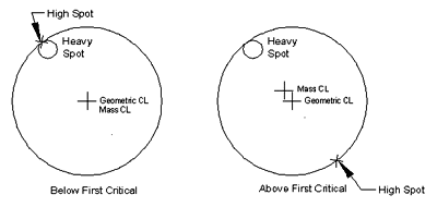
A definable relationship exists between the heavy spot and the high spot which depends
upon the rotor critical speed. If a rotor never experiences a critical speed throughout
its operating range the heavy spot will always be the exerting force resulting in the high
spot coinciding with the heavy spot, just as a weight being swung on a string exerts a
displacing force on the rotation axis.
As the rotor surpasses the first critical speed the heavy spot and high spot split
apart until the they are separated by about 180 . This phenomenon occurs because the rotor
now rotates around its mass centerline instead of its geometric centerline, forcing the
high spot to be the location of maximum displacement. If the rotor continues to increase
its speed and experiences another critical speed the high spot rotates another 180 until
the high spot coincides with the heavy spot. This 180 shift in the high spot's
relationship to the heavy spot continues as subsequent critical speeds are surpassed. For
further discussion about the relationship between critical speeds and the associated phase
shift, see STI Application Note, System Response (F=MA).
Correcting an unbalance condition involves using phase measurements to locate the high
spot orientation, determining the relationship of the high spot to the heavy spot, and
finding the magnitude of the unbalance by measuring the influence of correction weights.
Careful observation of the machine vibration level and phase angle as it progresses from
stand still to full operating speed will identify whether the trial weight should be
installed at the high spot phase angle or opposite the high spot phase angle. Following
this observation the vibration amplitude levels will almost always be reduced during the
first balance run, which usually impresses the machine operators.
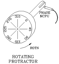
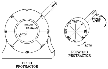 Two balancing procedures prevail: the fixed protractor method where a mark on the rotor
is used for phase measurements with a strobe light; the rotating protractor method where a phase transducer
observing a once-per-turn event is used for phase measurements. Both methods are a trial
weight balancing procedure where an initial weight is installed to determine how the rotor
responds to it.
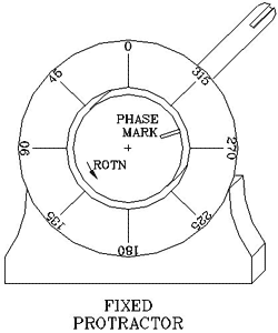
Fixed Protractor Method
In the fixed protractor method a strobe light is usually used to measure the phase angle
by observing a single mark, or unique item, such as a key or machined hole. Some procedures use a optical
tachometer, instead of a strobe light, to obtain phase measurements. Phase angle markings
are made on the stationary part of the machine. This method counts increasing phase angles
in the direction of rotor rotation. Phase measurements are taken by observing a single
mark on the rotating shaft using the strobe light which is tuned to the machine speed or
using the photo-tach which observes a piece of highly reflective tape placed on the shaft.
This method is commonly employed on machines that do not operate above their first
critical speed because the high spot and the heavy spot are coincident meaning that the
final balance weight location will be opposite the measured high spot. Also,
instrumentation setup is easy, usually using surface mounted vibration transducers.
Rotating Protractor Method
The rotating protractor procedure utilizes a phase Eddy Probe or an optical tachometer to
determine the phase
angle.
The trigger for this method comes from a pulse signal observing a once-per-turn event,
such as a keyway or a key. Phase angle measurements are the relation between the keyway
and the high spot, with increasing phase angles measured against shaft rotation.
Setup for this method requires that the phase transducer be installed observing a
once-per-turn event. An existing key or keyway is ideal, but if non-existent a temporary
key may be epoxied in place.
The rotor will require phase marks installed, not to directly obtain measurements, but
to assist in weight placement. A simple method for marking the shaft is to use a permanent
marker to label the rotor with the zero degree angle aligned with the keyway that the
phase transducer observes. When marking the rotor remember that phase increases against
the rotor rotation direction.
Trial Weights
Regardless of which balancing procedure used a "trial weight" is must be
installed to measure how the rotor will respond to this weight. This weight will induce a
different balance condition with an accompanying change in the vibration level and/or
phase angle. This change, once introduced into balance calculations, will dictate how much
weight is required to be added and the radial location for weight placement.
If the vibration levels are not acceptable after
a balance weight has be placed on the rotor, a further weight called a trim weight can be
installed. Sometimes this weight will be required to be located at a slightly different
location than the previous weight.
Balance Weights
Trial, balance, and trim weights may be made from any material. Common materials are
bolts, washers, or C- clamps. Strong tape, such as duct tape, is sometimes used to
temporarily attach a trial weight. Some machines will require an imagination to devise an
attachment method. Other machines, such as turbo- machinery, have balance weight holes
provided which may require some machine disassembly to access them.
If the weight must be located at the same location as a previous weight both weights
(previous balance weight and trim balance weight) should be combined into a single weight
by making a larger weight or using a material of greater density.
All weights, regardless of material or attachment method, must be held rigidly in
place. This may be accomplished by staking, welding, etc. Relying on a bolt and nut with
split washer should not be considered. If a bolt and nut configuration is used the bolt
should have its threads staked to prevent the nut from shifting.
Balancing Speed
Operating speed has a drastic effect upon the measured unbalance vibration level since the
centrifugal force due to unbalance is proportional to speed squared ( rpm). During the
balancing procedure the operating speed at which amplitude and phase measurements are
gathered must be held steady at a predetermined speed. All subsequent balance attempts
should be made with the machine operating at the same speed as previous attempts. Future
balance activity should be made at this same speed so that the balance response
coefficient(s) can be include into calculations to reduce the number of machine restarts.
Balance Response Coefficient
Once a rotor has been balanced, or has had a trial weight installed that produces a change
in vibration amplitude or phase, an unbalance constant can be calculated which can be used
in future balance attempts. Each rotor will have a different unbalance constant, given in
units of weight per amplitude (lbs/mil, oz/mil, gm/in/sec, etc.). A single plane balance
procedure will produce one balance response coefficient. Multiple plane balancing will
produce any number of coefficients depending upon the number of balance planes. A three
plane balance procedure will produce nine balance response coefficients. This number is
because as the trial weight is moved to each subsequent balance plane two additional
response coefficients are calculated.
Correction Weight Calculations
Once the vibration levels and phase angles have been collected with and without a trial
weight, the required correction weight can be calculated. Basically, the correction weight
must be sized to counteract the centrifugal force generated by the existing unbalance
mass. The method for calculating the weight differs depending upon the whether the rotor
experiences a critical speed and the number of balance planes.
One plane balance, operation below 1st critical speed
CW = (G X CF) / (R X SPD)
where CF = (V X K) / 2
and K = WR X M
Two plane balance, operation below 1st critical speed
Inboard CWi = (CFi X G) / (Ri X SPD)
where CFi = (Vi X Ki) / 2
and Ki = (WR X M) / 2
Outboard CWo = (CFo X G) / (Ro X SPD)
where CFo = (Vo X Ko) / 2
AND Ko = (WR X M) / 2
One plane balance, operation above 1st critical speed
CW = (CF X G) / (R X SPD)
where CF = (WT X V X SPD) / 2 G
Two plane balance, operation above 1st critical speed
CWi = (CFi X G) / (Ri X SPD)
where CFi = ( WT ) X Vi X SPD / 2 G
CWo = (CFo X G) / (Ro X SPD)
and CFo = ( WT) X Vo X SPD / 2 G
- CF = Centrifugal force due to unbalance (lbs)
- WR = First critical speed (rpm)
- K = Rotor spring constant (lb/in)
- M = Rotor mass (rotor weight (lb/G)
- G = Acceleration of gravity (386.4 in/s)
- V = Peak-peak vibration (in)
- SPD = Balance speed (rpm x 0.1047 rad/s)
- CW = Correction weight (lbs)
- R = Balance weight radius (in)
- WT = Rotor weight (lbs)
- CFi = Inboard centrif. force due to unbalance (lbs)
- Ki = Inboard rotor spring constant (lb/in)
- Vi = Inboard pk-pk vibration (in)
- CWi = Inboard correction weight (lbs)
- Ri = Inboard balance weight radius (in)
- CFo = Outboard centrif. force due to unbalance (lbs)
- Ko = Outboard rotor spring constant (lb/in)
- Vo = Outboard pk-pk vibration (in)
- CWo = Outboard correction weight (lbs)
- Ro = Outboard balance weight radius (in)
Balancing Checklist
- Balancing Method
- Trial Weight(s)
- Weight Material
- Balancing Speed
- Response Coefficient(s)
- Final Weight Placement Documented
|