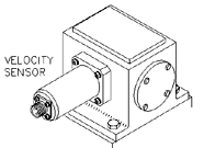
 The velocity pickup is a very popular transducer
or sensor for monitoring the vibration of rotating machinery. This type of vibration
transducer installs easily on machines, and generally costs less than other sensors. For
these two reasons, this type of transducer is ideal for general purpose machine
applications. Velocity pickups have been used as vibration transducers on rotating
machines for a very long time, and they are still utilized for a variety of applications
today. Velocity pickups are available in many different physical configurations and output
sensitivities. The velocity pickup is a very popular transducer
or sensor for monitoring the vibration of rotating machinery. This type of vibration
transducer installs easily on machines, and generally costs less than other sensors. For
these two reasons, this type of transducer is ideal for general purpose machine
applications. Velocity pickups have been used as vibration transducers on rotating
machines for a very long time, and they are still utilized for a variety of applications
today. Velocity pickups are available in many different physical configurations and output
sensitivities.
Theory of Operation
When a coil of wire is moved through a magnetic field, a voltage is induced across the end
wires of the coil. The induced voltage is caused by the transferring of energy from the
flux field of the magnet to the wire coil. As the coil is forced through the magnetic
field by vibratory motion, a voltage signal representing the vibration is produced.
Signal Conventions
A velocity signal produced by vibratory motion is normally sinusoidal in nature. In other
words, in one cycle of vibration, the signal reaches a maximum value twice in one cycle.
The second maximum value is equal in magnitude to the first maximum value, but opposite in
direction. By definition velocity can be measured in only one direction. Therefore,
velocity measurements are typically expressed in zero to peak, RMS units. RMS units may be
specified on permanent monitor installations to allow correlation with information
gathered from portable data collectors.
Another convention to consider is that motion towards the bottom of a velocity
transducer will generate a positive going output signal. In other words, if the transducer
is held in its sensitive axis and the base is tapped, the output signal will go positive
when it is initially tapped.
Construction
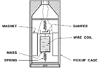 The velocity pickup is a self-generating sensor requiring no external devices to produce a
vibration signal. This type of sensor is made up of three components: a
permanent magnet, a coil of wire, and spring supports for the coil of wire. The pickup is
filled with an oil to dampen the spring action. The velocity pickup is a self-generating sensor requiring no external devices to produce a
vibration signal. This type of sensor is made up of three components: a
permanent magnet, a coil of wire, and spring supports for the coil of wire. The pickup is
filled with an oil to dampen the spring action.
Due to gravity forces, velocity transducers are manufactured differently for horizontal
or vertical axis mounting. With this in mind, the velocity sensor will have a sensitive
axis that must be considered when applying these sensors to rotating machinery. Velocity
sensors are also susceptible to cross axis vibration, which if great enough may damage a
velocity sensor.
Wire is wound onto a hollow bobbin to form the wire coil. Sometimes, the wire coil is
counter wound (wound one direction and then in the opposite direction) to counteract
external electrical fields. The bobbin is supported by thin, flat springs to position it
accurately in the permanent magnet's field.
Special Considerations
Number of Sensors
All vibration sensors measure motion along their major axis. This fact should be
considered in choosing the number of sensors. Due to the structural asymmetry of machine
cases, the vibration signals in the three axes of motion may differ. Where practical, a
velocity sensor should be mounted in the vertical, horizontal, and axial planes to measure
vibration in the three directions. The three sensors will provide a complete definition of
the vibration signature.
Mounting
For the best frequency response, the mounting location must be flat and 10% larger than
the velocity pickup, or if used a separate mounting enclosure. The surface will require
drilling and tapping to accommodate the mounting of the sensor.
Sensitivity
Some velocity pickups have the highest output sensitivities of any vibration pickup for
rotating machine applications. The sensitivity will vary from manufacturer to
manufacturer. The higher output sensitivity is useful in situations where induced
electrical noise is a problem. The larger signal for a given vibration level will be less
influenced by the noise level. Some velocity pickups with their sensitivities are listed
below:
| Sensitivity |
| STI
CMCPWIL793V |
100 mv/in/sec |
Frequency Response
Velocity pickups will have differing frequency responses depending on the manufacturer.
However, most pickups have a frequency response range in the order of 10 to 1000 hz. This
is an important consideration when selecting a velocity pickup for a rotating machine
application. The pickup's frequency response must be within the expected vibration
frequencies of the machine. Due to the support spring for the bobbin, a natural
mechanical resonance occurs at the low end of the frequency response curve. This resonance
is either damped by the oil contained within the sensor, or with a shunt resistor across
the coil's leads.
Calibration
No calibration of the velocity pickup is necessary, however, on an annual basis the sensor
should be removed from service for a calibration verification. Verification is required
because velocity pickups are the only industrial vibration sensor which has internal
moving parts that are subject to fatigue failure.
This verification should include a sensitivity response versus frequency test. This
test will determine if the internal springs and damping system have degraded due to heat
and vibration. This test should be conducted with a shake table capable of variable
amplitude and frequency testing.
Instrument Wire
The following table is a partial list of Belden® Cables that should be used for the
instrument field wiring. These part numbers may be cross referenced to equivalent cables
from other manufacturers. The listed cables are polyethylene insulated, twisted, with
Beldfoil shield, drain wire, and PVC jacket.
| Belden® Part Numbers |
| P/N |
Nom. O.D. |
| 18 AWG |
8760 0.22" |
| 20 AWG |
8762 0.20" |
| 22 AWG |
8761 0.18" |
Common Point Grounding
To prevent Ground Loops from creating system noise, system common, ground and instrument
wire shield must be connected to ground at one location only. In most cases, the
recommendation is to connect commons, grounds and shields at the Monitor location. This
means that all commons, grounds, and shields must be floated or not connected at the
machine.
Occasionally, due to installation methods, instrument wire shields are connected to
ground at the machine case and not at the monitor. In this case, all of the instrument
wire shields must be floated or not connected at the monitor.
Conduit
Dedicated rigid conduit should be provided in all installations for mechanical and noise
protection. The conduit should be metal, and in direct contact with each segment. All
metal junction boxes and fittings should be in direct contact with the conduit. With this
type of installation, a single ground point can be established.
To facilitate removal of the velocity pickup, a junction box with a barrier terminal
strip should be located close to the transducer. The rigid conduit should be attached to
the junction box and the final run to the pickup can be metal flexible conduit.
Velocity Pickup Checklist
- Velocity Sensor Type
- Number of Sensors
- Sensitivity
- Frequency Range
- Correct Instrument Wire
- Rigid Conduit
- Grounding
- Location(s) Documented
- Calibration Check
|