Improve Reliability and Performance with a TSI from STI Vibration Monitoring
STIs Turbine Supervisory Instrumentation (TSI) Systems provide continuous on-line monitoring and machine protection for steam and gas turbine generator sets. The TSI system measures a variety of supervisory parameters to provide Operationsreliable machine condition information and alert them to any machinery problems. STIs philosophy of using a modular, distributive monitoring approach, coupled with utilizing existing plant networks where possible, result in an extremely cost effective solution for monitoring a turbine generator set.
Design your TSI System to meet your plant requirements
Using our modular approach, you can build a TSI system to fit your plants monitoring needs, and allow for cost effective expansion or updates to your TSI. Choose between condition monitoring and machine protection, analog outputs or digital communications to your DCS. Utilize existing sensors that are still functional, and minimize signal wire installation by installing the system local to the turbine generator. A cost effective alternative to traditional control room mounted 19 rack based systems is here to ensure your system comes in on-time and within budget.
Wide variety of TSI Modules
STI offers a comprehensive selection of modules to monitor all your desired TSI functions.
These include:
Shaft Relative Vibration: Eddy Probe systems measure the dynamic motion (radial vibration) of the rotor shaft relative to the bearing housing. This parameter will detect common machinery problems such as rubs, imbalance, bearing stability, etc. Eddy Probes also provide a measurement of the shaft position within the bearing clearance, giving warnings of harmful preloads and misalignment.
Absolute Vibration: For machines with a light casing to rotor weight ratio, vibration is readily transmitted to the bearing housing. An accelerometer or velocity transducer is a cost effective vibration sensor for these machines.
Thrust Position: Thrust position is the Eddy Probe measurement of axial movement of the rotor when the machine is running under load. Excessive horizontal movement of the rotor can result in catastrophic damage in mere seconds. It is common to use two Eddy Probes when deciding to utilize automatic shutdown on a Danger Alarm indication.
Eccentricity: Eccentricity is the measurement of Rotor Bow at slow roll by an Eddy Probe. It may be caused by any or a combination of a fixed mechanical bow, misalignment, temporary thermal bow, or a gravity bow. It is also may be used to calculate shaft attitude angle, which is an indicator of rotor stability.
Speed: An eddy probe or magnetic pickup may observe a key, notch or gear. The signal may be interfaced to a transmitter, tachometer, or used for Zero Speed for turning gear engagement.
Phase: Phase angle is the relationship of one vibration signal to another vibration signal and is expressed in degrees. It is not usually continuously monitored, but is available as a diagnostic aid in vibration analysis and balancing. An Eddy Probe is typically used to observe a once per turn event such as a key or a notch.
Case Expansion: Case Expansion is the relation of the shell or case in relation to its foundation. Turbine generator sets are tied down at one end and allowed to thermally expand at the other. An LVDT is used to measure this thermal growth, which on large machines can be several inches. Many customers choose to monitor both sides of the front standard to ensure that the case is thermally expanding evenly.
Valve Position: Valve position is measured with a LVDT observing the cam shaft rotation. It is an indicator of turbine load when the machine is on-line.
Differential Expansion: Differential expansion on a turbine is the relative Eddy Probe measurement of the rotors axial thermal growth with respect to the case. Differences in thermal growth of the rotor to case growth can lead to rubs and catastrophic failure.
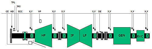
Legend:
CE: Case Expansion
KØ: Phase Reference & Speed
TP1: Thrust Position One
TP2: Thrust Position Two
ECC: Eccentricity
X: Radial Vibration, Horizontal
Y: Radial Vibration, Vertical
VP: Valve Position
DE: Differential Expansion
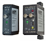
CMCP500 Series Transmitters / Monitors
A/D Converters
STI provides a modular, DIN rail mounted A/D converters in 8 or 16 channel configurations to interface to your plant network and further reduce your installation cost. TSI Signal wiring requires shielding and protection, and proves to be one of the highest cost in a TSI installation. By locating transmitter/monitors locally to the turbine deck and interfacing to a small local A/D, we can significantly reduce the installed cost of the TSI system while ensuring the highest level of reliability. Our standard communications offerings include MODBUS RTU or Ethernet. Please advise us if you have a different protocol requirement.
Wonderware® System Integration
STI is an authorized Wonderware system integrator. We will customize a graphical Operator display station with Machine Mimics, Current and Historical Alarm list, Trends, Fast Trends, System Configuration screens, etc. Wonderware is the largest selling HMI system in the world, with thousands of drivers to interface with all major PLCs, DCS and PCs.
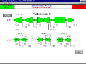 |
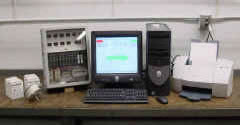
CMCP500 TSI with MODBUS RTU A/D, PC, 17 Display, Printer, and Wonderware Operator Interface Screens |
Turnkey Supervision
STIs experience in managing complex TSI projects will help you get your system installed on time and within budget. STI will provide an experienced field engineer to develop a scope of work, obtain appropriate sub-contractors, design probe brackets, project management, site supervision, system commissioning, and on-site training.
STI has performed dozens of turn-key installations throughout North and South America and Korea. |